Here are answers to some Frequently Asked Questions (FAQs) we have gotten about modeling CFIS systems in Ekotrope:
My CFIS system has a positive airflow, but it shows zero CFM under the ASHRAE 62.2 QA checks. Why is my ventilation system failing the minimum ventilation requirements?
If your CFIS system does not have a strategy to meet the ventilation remainder, then it does not qualify as dwelling unit mechanical ventilation, per the definition in ANSI / RESNET / ICC 301 (See the CFIS inputs table).
Ventilation will only be provided when the damper is open during heating and cooling hours. If the home's minimum ventilation requirements for the hour aren't filled during conditioning runtime, then the home will fail to meet the target. Therefore, it will automatically fail the requirements of ASHRAE 62.2 for ventilation systems.
There is a supply fan ducted into the distribution system and interlocked with the AHU, should this system be modeled as a CFIS, or CFIS with Supplemental Fan?
If the supply ventilation fan and the blower fan are interlocked (The supply fan and the AHU both run during conditioning hours, and the ventilation remainder), then the system should be modeled as a CFIS with Supplemental Fan. Specifically, the checkbox 'Does supplemental fan run simultaneously with blower fan?' should be checked.
How should I model an ERV ducted together with the Air Handler Unit, similar to a CFIS ventilation system? How should I model a CFIS system with energy recovery features?
Ekotrope RATER currently does not support modeling integrated ERV systems ducted together with the AHU, or CFIS systems with energy recovery features. This includes scenarios where the ERV fan is interlocked to run when the blower fan runs. There is a workaround we suggest that might approximate this system though.
The CFIS ventilation type in the app does not support any energy recovery, so it can't be used to represent this system. Instead, this system could be approximated with two separate ERV ventilation components, one to represent the ventilation system during conditioning hours, and one to represent the system during the ventilation remainder.
The 1st 'conditioning' ERV should be modeled with the combined airflow and wattage of the AHU plus the ERV fan. The runtime should be modeled with an estimation of the annual average conditioning hours per day. This value can be calculated by downloading the Hourly Results export.*
If the blower fan and the ERV fan are not interlocked, the 2nd 'ventilation' ERV should be modeled with only the airflow and wattage of the ERV fan. The runtime should be set to the expected remainder of time required for meeting the ventilation target. The downside with this modeling approach is that it won’t work like a CFIS with supplemental fan; the ERV will not make the blower fan run during the ventilation-only hours. Non-CFIS mechanical ventilation does not share controls with the blower fan in our energy model. The upside is that the energy recovery of the system is captured, and that if the ERV wattage represents the AHU fan power plus the ERV fan power, the blower fan consumption during ventilation runtime will be approximated.
If the blower fan and the ERV fan are interlocked, the two ERV components could be combined into one, with the inputs set to the sum of the airflow, wattage, and runtimes for the AHU and ERV together. This method will not perfectly represent an ERV ducted together with an AHU; the blower fan consumption may be double counted during actual conditioning hours. But it is a conservative approximation of the results for this system, given the current limitations with the RATER model.
An example system. The AHU produces 75 CFM of airflow for 30 Watts, and the ERV fan produces 25 CFM of airflow for 10 watts. The 'conditioning' ERV on the left represents the combined AHU and ERV runtime, while the 'ventilation' ERV on the right represents the ERV fan running alone during the ventilation remainder.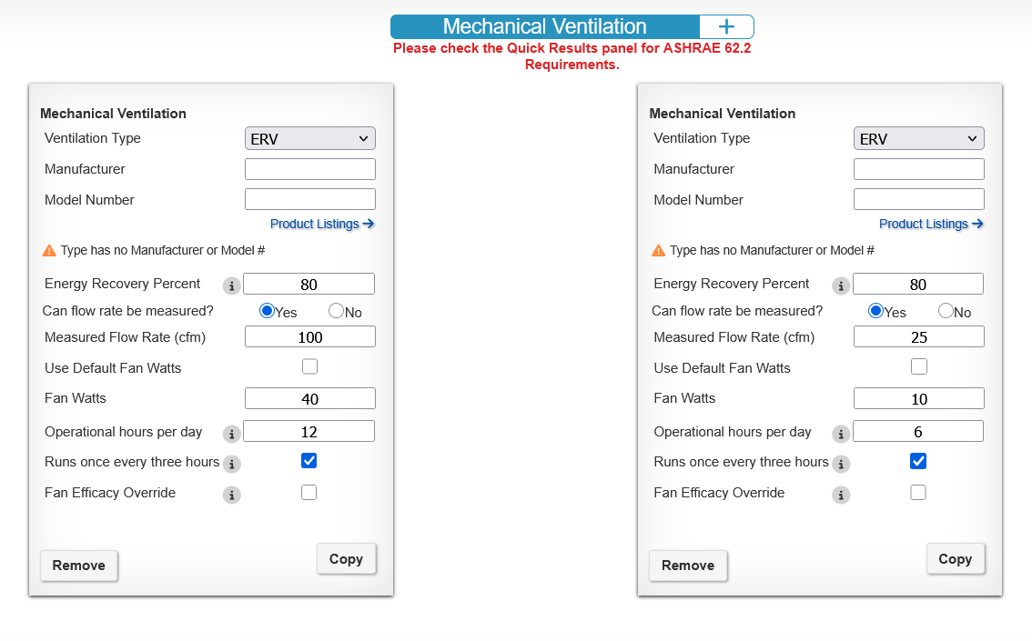
*If you want to get an average estimate of the fraction of the day that the conditioning systems will run, you could follow these steps:
1. Download the Hourly Calcs for your design. If you don't have this option available, contact support@ekotrope.com.
2. When the Adjusted Load column (K) is positive, divide the value by the capacity of your heating system. When the Adjusted Load column is negative, divide it by the capacity of your cooling system. The Adjusted Load column is given in MBtu/h, whereas your capacity is given in kBtu/h, so you will need to convert your units. This gets the fraction of the hour that each system is running.
3. Sum these fractions of each hour over the year.
4. Divide that sum by the number of hours in the year (8760) to get the average fraction of an hour that your conditioning system is running.
5. Multiply that value by 24 to get the fraction of the day.
Was this article helpful?
That’s Great!
Thank you for your feedback
Sorry! We couldn't be helpful
Thank you for your feedback
Feedback sent
We appreciate your effort and will try to fix the article